ZENITH DEFY ANALOG QUARTZ LED 1975
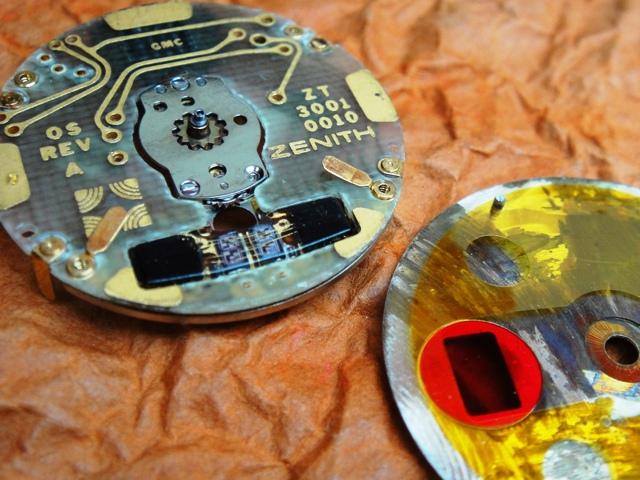
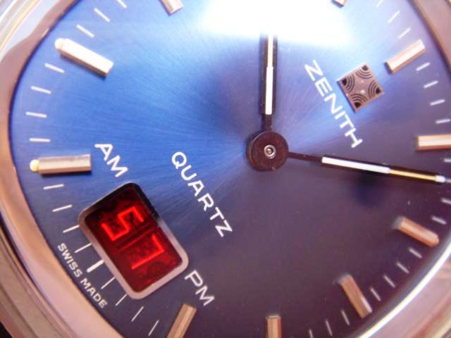 In 1975/76 Zenith introduced the "Time Command" series of analog-digital quartz watches with a LED indicator for seconds and date. Most top-shelf manufacturers never produced electronic watches which were subcontracted and branded to suit demand in certain markets. It's difficult to say if the "Time Command" was an inhouse invention by Zenith as the modules were made in Korea probably by AMI (despite being advertized as Swiss Made). The modules seem to be standard analog quartz movements but without a typical gear train. The mechanical assembly is limited to three gears "kicked" directly by the large stepping motor that produces an impulse once per minute. A smart concept has been applied by removing a typical minute wheel - the cannon pinion and hour wheel rotate on an elyptical path thus limiting the number of parts.
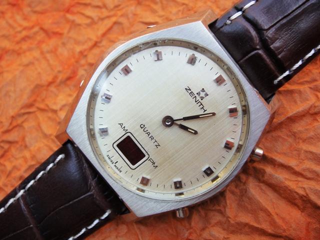
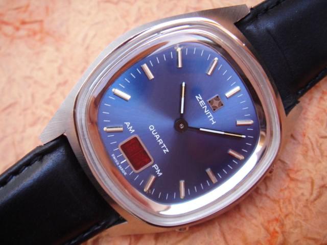
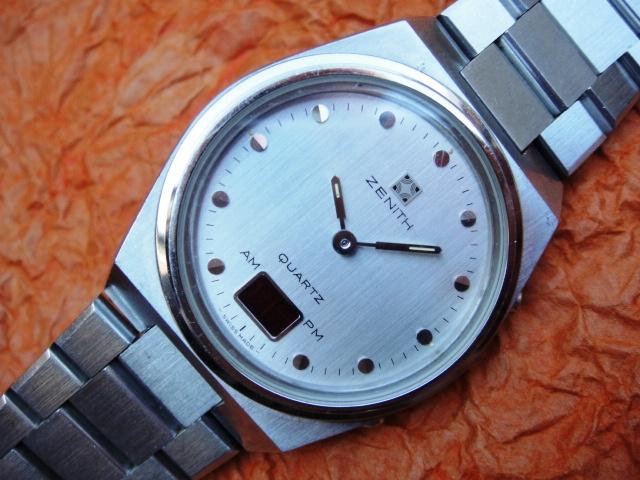
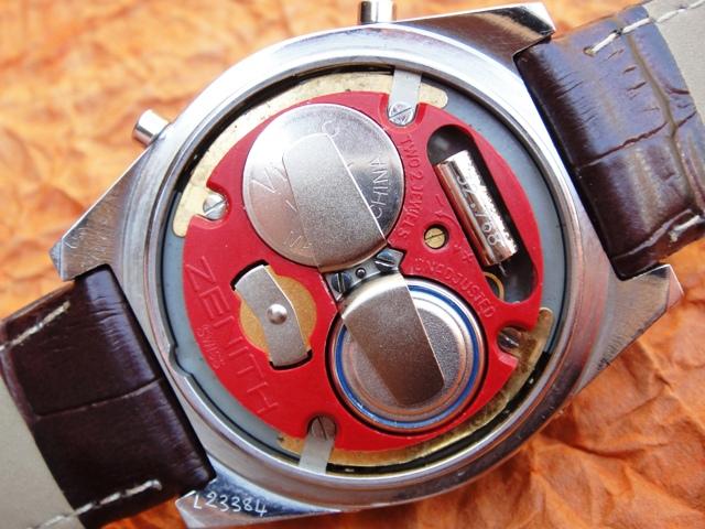 The oval types shown above are the most common (sometimes branded Zenith Defy). They all utilize the same base module as the square "Futur" with the slight difference of having a dislocated LED indicator. Transplanting the entire LED assembly from a round Defy to a square Futur is possible with some soldering. These modules are totally overengineered thus any kind of smallest issue within one of the assemblies results in complete malfunction. Hints: 1) The battery contacts/springs are fitted permanently to the plastic carrier and might be missing (broken). A replacement option is shown below. The slightly raised pins must provide excellent connectivity with the corresponding points on the circuit board. Insufficient or extensive pressure from the batteries, oxidation or battery residue will result in malfunction.
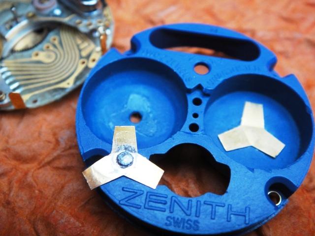
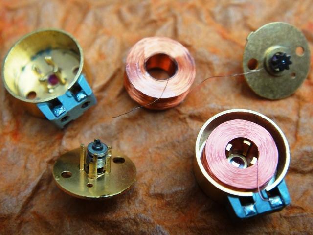 2) The battery wells are not described thus people tend to place both batteries incorrectly. Fortunately it is possible to notice that the wells are curved differently at the bottom. 3) The motor assembly is pretty safely encapsuled as shown to the left and consists of an insulated coil and permanent magnet fixed to a jeweled center post. The coil indicates a proper resistance of 0.46-0.50 kOhms but intensive battery leakage might damage it or at least the wire-tips soldered to the external contacts. If only the wire-tips are broken you can unwind one turn of the wire and resolder to the contacts. This will reduce resistance slightly and will still work however any greater difference from the above values will mean that the coil is beyond repair. Do not use to much heat as the soldered contacts are fitted to a piece of grey plastic.
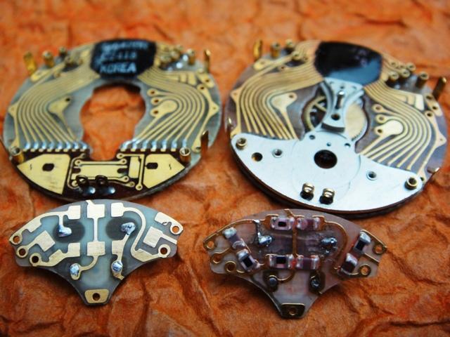
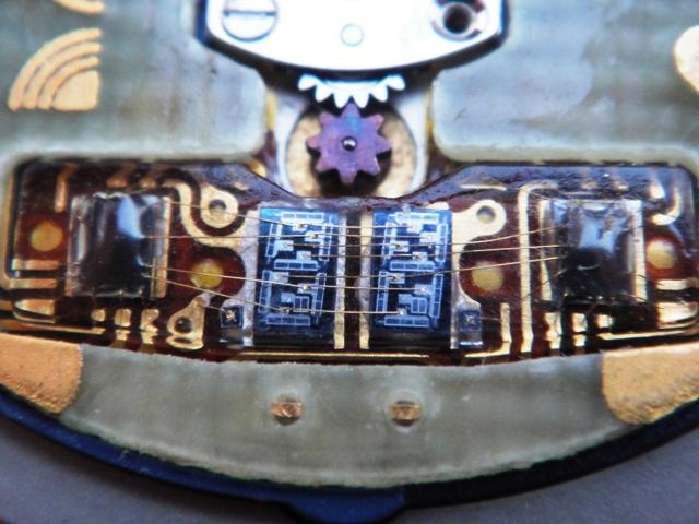
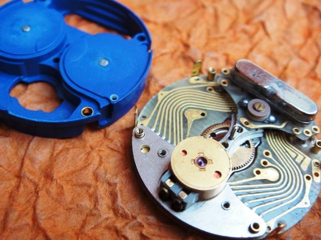
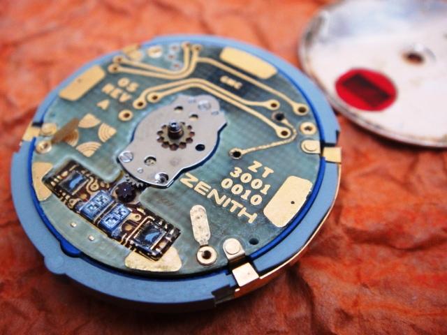
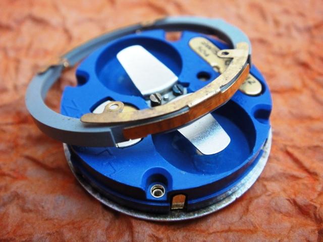 4) The quartz assembly is fitted with 6 screws to the main board and must provide excellent connectivity. The trimmer might need to be cleaned or replaced including the quartz tube (most common issue). Resistors/capacitors on the bottom side of the quartz assembly might be busted and result in total malfunction. 5) Missing segments/digits on the LED indicator might be caused by bad solder joints between the LED assembly and main circuit board and can be easily improved. This issue might also be caused by corrupt drivers that are completely sealed with silicone together with the display and thus unrepairable. Occasionally shorting the exposed LED traces might bring a driver back to life but the chance is minimal. 6) The module is connected with the case by means of gilded button contacts on the grey external ring (shown right). These contact plates (that might be broken) are screwed onto the module and close the circuit when depressed.
Keywords: zenith led, zenith time command, zenith defy
Market value: 75-450$ (condition, box)